Point entities define a single point in space. They have no size, although they are drawn on the screen using some type of user-defined tick mark (the default is a small circle). For boat design, point entities are mostly used to define target points where the hull has to pass through. Since points do not have any size, they cannot be used to define surface geometry of a boat, but they can be used for a variety of other tasks. (See the tutorial on creating a new boat to see how points can be used for defining target hull points.)
The following section discusses the process of defining, modifying, and deleting point entities.

This screen image shows an empty ProSurf screen with 5 point entities entered at arbitrary locations. These points were defined as follows:
1. Pull down the Point menu commands and select the "Add Point" command. This will turn on the add-point command and make it the "current" command (see the command label shown in the lower right corner of the screen).
2. To add a point entity, position the cursor anywhere and "click" the left mouse button.
3. Each time you "click" the left mouse button, a new point entity is created at the current cursor location.
4. The "Add Point" command will stay current until you select another command. Always look in the lower right corner of the window to see the current command.
Later on, you will see how to set a point to a specific [X,Y,Z] position, if necessary.

All geometric entities have properties or attributes associated with them, such as point type and entity color. This screen shows an attribute dialog box for one particular point entity. It was displayed as follows:
1. Pull down the Point set of commands and select the "Point Attributes" command. Nothing will happen except that this becomes the "current" command and the label "Point Data" is displayed in the lower right corner of the window.
2. Move the cursor near one of the point entities and "click" the left mouse button.
3. A dialog box, like the one shown above, will appear..
4. The attribute fields are:
Point Name - The point's name, created by the program. You can change it, if you wish.
Point Type - The type of symbol to use to mark the point's position.
Overlay - The overlay layer of the entity. (Currently not used by the program)
Color - Color to use for the point's marker.
Draw Point - Option to turn off the display of the entity. Use the Display All Points command to turn
on the display of the point.
Edit Point - This allows you to display the point, but to disable the ability to change its position.

Once you have some points defined, you need to be able to modify their positions. The commands to do this are located in the "Edit" pull-down menu, as shown above. Right now, you will find out how to use the Move Point and Set Point commands. The Move, Rotate, and Scale Entity commands will be discussed in another tutorial. Keep in mind that the Move Point and the Set Point commands will be used for points defining all entity types (lines, curves, surfaces, etc.).

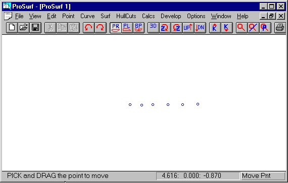
This screen shows how all of the point entities were moved by eye to form a straight line. This was done as follows:
1. Pull down the "Edit" set of commands and select the Move Point command. You will notice that the "Move Point" label is displayed in the lower right corner, since this is now the current command.
2. Place the cursor near one of the points you wish to move.
3. Press and hold down the left mouse button.
4. Drag the point (mouse) to the desired new position.
5. Release the left mouse button.
The dragged point will now be located in its new position. You can now repeat the process with the same or any other point on any type of entity.
If you want the point to be located in some specific position, see the Set Point command explained below.

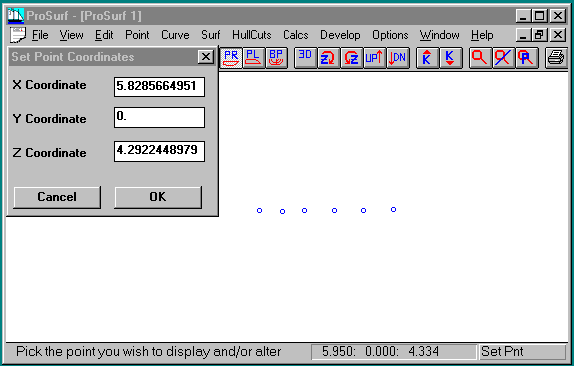
This screen shows the position dialog box for a particular point. It was displayed as follows:
1. Pull down the "Edit" set of commands and select the "Set Point" command. You will notice that the "Set Pnt" label is displayed in the lower right corner, since this is now the current command.
2. Place the cursor near one of the points you wish to set.
3. "Click" the left mouse button.
4. A dialog box, like the one above, will be displayed.
5. Make your changes and select OK, or Cancel to ignore. Many times this command is used just to determine the coordinates of a point.
You can change any or all of the coordinate values. Note that sometimes the full number will not appear in the visible field. This will require you to place the cursor in the field and press the "Home" and "End" keys.